Fred's Tamiya 58636 TA07 Pro Build
Build Article:
After many years on the design table, the ALL NEW TA-07 on-road chassis is here! The TA-07 comes as a “PRO” kit. The Pro kit is designed to give enthusiasts a taste of some of the option parts that make it stand out over a basic kit. Rest assured, there is plenty of room to add existing Tamiya Hop-Up Options and accessories to personalize your machine along with many NEW option releases to come soon.

The Tamiya instruction manual is excellent, but I will illustrate little tricks that the manual doesn’t go over so that you get the best possible build out of your new racing kit. Along the way I will also go over the Hop-Up Option parts that I have put into my test car. These are the parts I believe further enhance the potential of the new TA-07 platform.
The article goes over the build in the same order as the manual. In a lot of the steps I will point out key things to pay attention to, while in other steps there won’t be anything significant to call out.
Step One:
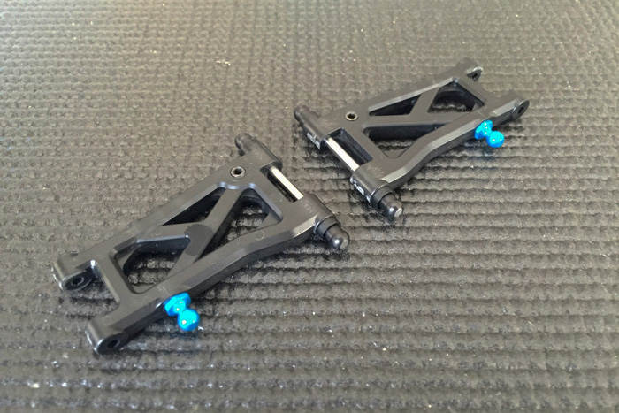
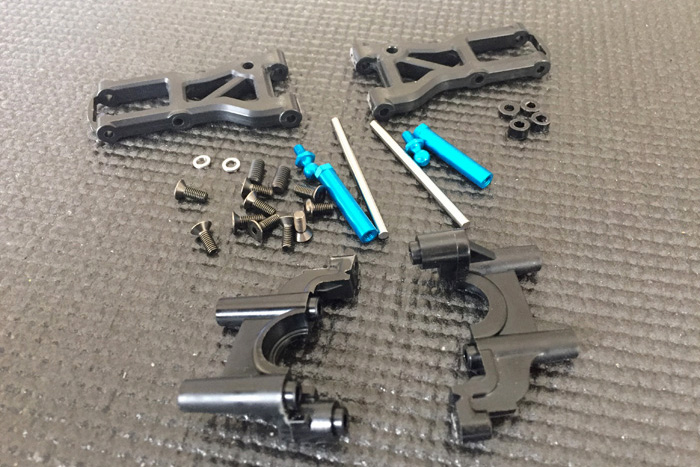
Step one is about building the rear suspension arms. Make sure to remove any excess plastic flash and mold lines from the rear suspension arms. I specifically recommend using a flat steel file to remove any flash between the outer suspension arm areas where the REAR hub carrier will fit in between. Next, make sure that the chrome hinge pins slide through the suspension arm smoothly. If they do not slide smoothly, go ahead and slightly ream out the hole with a 3mm reamer. In my kit the suspension arms did not need to be reamed out. The suspension shafts slid very smoothly with no further attention required.
 Tamiya Side Cutters come in handy to remove the part from the tree.
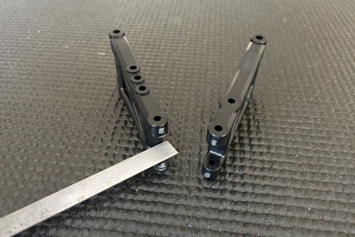 Use a flat file to remove any excess mold flash that may interfere with the hub carrier.
Next, make sure to apply Tamiya Anti-Wear grease between the hinge pin and the suspension ball. I prefer to use the Tamiya Fluorine Coating Liquid (Item 42280). It’s silky smooth and it attracts less grime compared to using the Tamiya Anti-Wear Grease. Either lube is fine to use, just make sure to use one or the other. Running the parts dry will wear out the suspension balls out prematurely.
Building upgrade tip:
Parts A1 are used as spacers to adjust wheelbase with your suspension arm. They are made of plastic. Item 53539 RC 5.5 Aluminum Spacer Set can be used in its place. The set comes with 6 different aluminum spacers so you can alter the wheelbase of your chassis. Adjusting the suspension arm position is a way to tune the handling of your car.
Step 2:
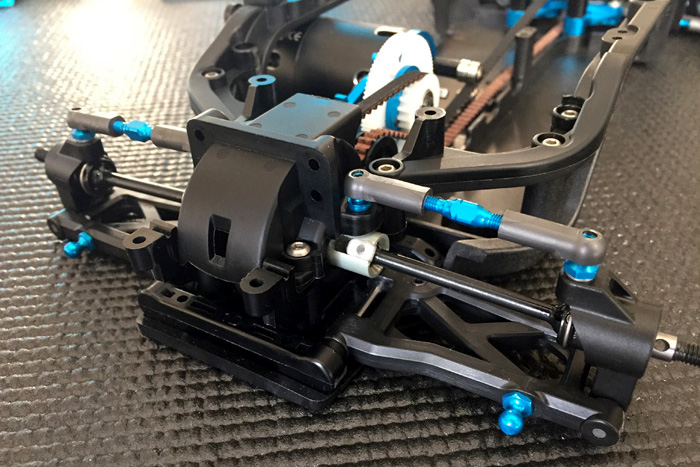
In step two you will be securing the suspension blocks to the main chassis and securing the rear suspension arms. At this point you have a choice to make in terms of upgrades. The standard Pro Kit comes with plastic suspension mounts. The mounts work fine, but they will wear out faster and flex more compared to the aluminum Hop-Up Option mounts. For my test car build, I choose to upgrade to the aluminum suspension mounts. The kit plastic rear suspension mount set up consists of the following mount dimensions: Inner 1A/1XA and outer 1D. This set up gives you a standard rear toe-in setting of 2.5 degrees. If you want to match the kit setting you will need Hop-Up Option items 54172 TA05V Separate Suspension Mount 1A/1XA and item 54072 TB-03 Suspension Mount 1D. Alternatively, you can also use the NEW Rigid Separate Suspension Mounts found on the TRF419/419X for the inner suspension mount position. To match the kit setting you will need items 54619 Rigid Separate Suspension Mount (1XA).

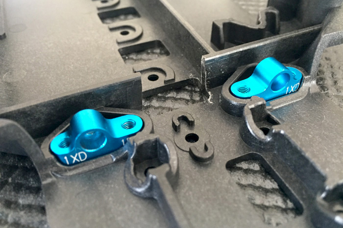 Separate Suspesion Mounts
 Rigid Separate Suspension Mount
Note:
What’s the difference between a Separate Suspension Mount and a Rigid Separate Suspension Mount? The Separate Suspension Mount is designed in such a way that you get two mount settings for the price of one. Instead of the mounts suspension ball being directly in the center of the block, the separate mount has the suspension ball hole offset. This allows you to flip the suspension mounts to get the desired setting of the two offered for that one mount. A Separate Suspension Mount that is labeled 1A/1XA can be flipped to give the user one of the two settings. The Rigid Suspension Mount is different. You lose the “two for one” setting, but you get a mount that is narrower and keys into the main chassis. There is a pin guide machined onto the mount, which allows the suspension mount to be further securely fastened. The TRF419 was the first Tamiya car to employ the Rigid Suspension Mount design. The TA07’s molded chassis allows you to use either type of mount. Whatever aluminum suspension mount you choose will be a significant upgrade from the standard plastic part.
Building Tip:
Make sure to add Tamiya Anti-Wear Grease or Fluorine Coating Liquid to the suspension ball before installing them onto the arm. This will prolong the life of the moving parts. It will also insure smooth movement.
Step 3:
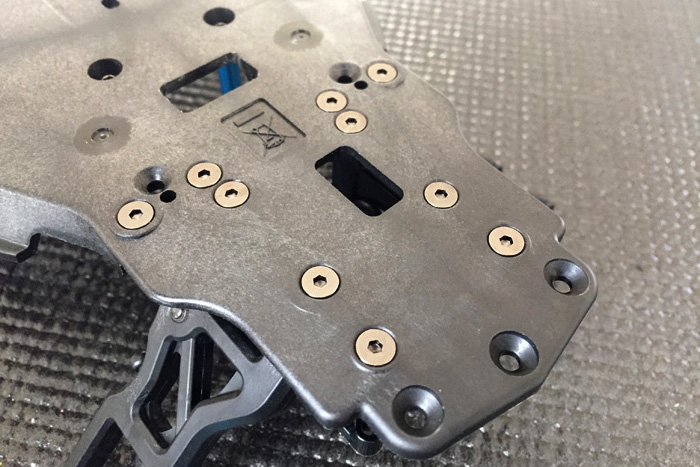
Step 3 is fairly straightforward. Simply bolt on the plastic bulkhead as shown in the manual. The TA-07 kit comes with Hex Head hardware, which makes it easy to torque the screws uniformly.
Step 4:
This step pertains to the front suspension arm assembly. As in step one, make sure to remove any plastic mold lines that will prevent free suspension shaft movement.
Building upgrade tip:
Parts M13 and M11 are used as spacers to adjust wheelbase. They are made of plastic. Item 53539 RC 5.5 Aluminum Spacer Set can be used in its place. The set comes with 6 different aluminum spacers so you can alter the wheelbase of your chassis.
Step 5:
In step five you will be securing the suspension mounts to the main chassis and securing the front suspension arms. At this point you have a choice to make in terms of upgrades. The standard Pro Kit comes with plastic suspension mounts. These mounts work fine, but they will wear out faster compared to the aluminum Hop-Up Option mounts. For my test car build I choose to upgrade to the aluminum suspension mounts like I did for the rear of the car. The plastic front suspension mount set up consists of the following mounts: Inner 1A/1XA and outer 1A. This set up gives you a front toe-in standard setting of ZERO degrees. You will need Hop-Up Option items 54172 TA05V Separate Suspension Mount 1A/1XA and item 54069 TB-03 Suspension Mount 1A to match the kit set up. Alternatively, you can also use the NEW Rigid Separate Suspension Mounts found on the TRF419/419X for the inner suspension mount. To match the kit setting you will need items 54696 Rigid Separate Suspension Mount 1A for the inner front suspension mount.
Note:
If you are not upgrading to the aluminum mounts, you may have to heed the note on the side of step 5. It mentions you might have to use smaller shims (supplied in the kit) to get the necessary freedom of motion with the suspension arms.
Step 6:
Step 6 is fairly straightforward. Simply bolt on the plastic bulkhead as shown in the manual.

Step 7:
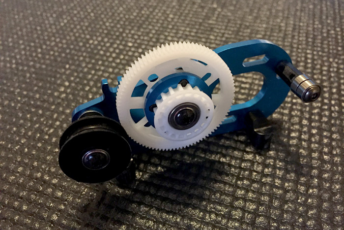
In this step you will install the spur gear onto the spindle. For this build I chose to use a 90 Tooth 64 pitch Panaracer gear. I choose a 90-tooth spur gear because it will allow me to get to the desired final drive ratio for the 17.5 motor I will be installing later.
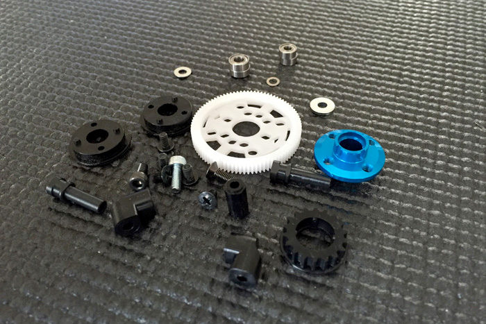
In this step you have the choice to use the kit supplied center pulley or one of two Hop-Up Option pulleys. The first option is to use the Hop-Up Option pulley that is made from a slide molding process and features integrated pulley flange to eliminate the risk of flange detachment. It was originally designed for the TRF501X, but it also fits the TA-07. The white material is smoother compared to the kit supplied plastic pulley. (Item 53989 RC Center Pulley 18T TRF501X).


The second choice is to use the TA-07 Aluminum Center Pulley 18T. This pulley has a low friction anodized finish that improves efficiency and torque output. (Item 54722 TA07 Aluminum Center Pulley 18T).
Step 8:
In step eight you will be putting together the spur gear assembly to the aluminum motor plate.
Part A-15 is made of plastic. In case you were wondering, there is not an aluminum option at this time, but hopefully we will see one announced at a later date. An aluminum version of part A-15 will better secure the motor plate to the main chassis.
Next, two plastic A-5 parts are secured together with CA cement. This will work, but I would opt to use the TA-07 Aluminum Counter Pulley (item 54706 RC TA07 Aluminum Counter Pulley) It is made of lightweight aluminum, provides excellent transmission of torque, and there is less chance of the belt skipping.


Step 9:
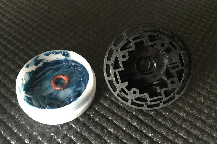
In this step you are going to build the included oil-filled gear differential units. For my build I choose to use 5000 weight diff fluid for the rear diff unit and 20,000,000 million for the front.

At this stage of the build you can choose some of the upcoming Hop-Up Options for this part of the drivetrain. For the rear you can install a Ball Differential Unit and for the front you can choose to install a Direct Coupler (Spool). Items 54690 and 54689 respectively. The spool will give the car sharper initial acceleration and more stability under deceleration. The unit is lightweight, which contributes to a lighter weight chassis. The ball differential will increase stability under low traction conditions, but under high traction it will be harder to drive the car around the track. Use these Hop-Up Options for tuning your car for the conditions of the track.
In my build I chose 20-million weight diff oil for the front gear diff unit because it gives me stability, good initial turn-in, and exceptional corner speed. 20-million front diff fluid also gives me “spool-like” driving characteristics.
Building Tips:
Use Tamiya Anti-Wear Grease (item 53439) to coat the brass bushing that will seat into the diff-housing. The Anti-Wear Grease will create a better seal.

Use Tamiya VG Damper Grease (item 42129) to coat the red O-ring. The VG Damper Grease will create a better seal for the diff unit.
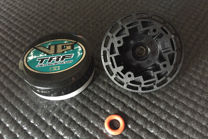

Lightly sand the paper gasket and apply VG Damper Grease. This process will create a better seal between the two differential gear halves.


To reduce rotating-mass use the Aluminum Diff Joint from the TRF419. The Diff Unit included in the TA-07 is the same as the TRF419/419X, so all you will need are spare part diff joints. (Item 51565) You will need two packages to complete one car.
You will also need item 51536. These are the Swing Shaft Caps (blades) that will fit onto your universal drive shafts.


The TRF419/X uses aluminum cross shafts inside the gear diff unit. You can also use them for the TA-07 if you chose to update the included plastic shafts (Item 9804852).

Some people replace the diff’s brass bushings with ball bearings. I don’t recommend it. Ball Bearings will cause the diff unit to leak. They don’t fit as tightly as the included brass bushings.
Step 10:
This step is straightforward. The only thing you need to decide is what motor position you want to begin with. I would recommend starting with the motor in the rear position first.

Step 11:
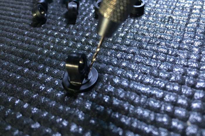
In Step 11 I chose to replace the kit included 5mm ball connector with the optional “Hex Head” ball connector (Item 53906). I like to use the Tamiya hex head ball connectors because I drill 2mm holes in all my 5mm adjusters (also known as ball cups). This process allows me to unscrew any linkages rather than using force to pop them off, which will shorten the life of the 5mm adjuster.


Step 12:
In step 12 I chose to use the Hop-Up Options that replace the kit standard plastic steering linkage parts. The kit parts work fine as they do include ball bearings, but I prefer to have more direct feel from the steering mechanism, which the aluminum version provides. You will need items 54705 TA07 Aluminum Steering Bridge and item 54704 TA07 Aluminum Steering Arm Set. Make sure to also use “Hex Head” 5x5mm aluminum ball connectors (Item 53906) instead of the included regular aluminum ball connectors. The Hex Head type will make your life easier when changing the steering spacer during your track days. You will have easy access from the front of the car if you need to change the steering spacer to alter Ackerman steering angle.


Steps 13-14:
Both of these steps are straightforward. Install the parts shown as directed. On step 14 be mindful to tighten the front stiffeners while the chassis sits on a flat surface.
Step 15:
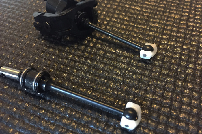
In this step you are going to build the front universals. If you plan to run a Direct Coupler (Spool) (Item 54690 TA07 Direct Coupler), I advise picking up a set of Double Cardan Universal shafts as I did. (Item 42216) The Double Cardan shafts will minimize rotational vibrations for better suspension feel. You’ll also notice your car will feel smoother when you turn the steering wheel.
The standard universals shown below.

Double Cardan Universal shafts shown below. Note: Make sure to use the ball bearings included with the Double Cardan Shaft Set. They are thinner than the kit supplied ball bearings. You need the thinner bearings for the Double Cardan Shafts to clear the steering knuckle.

Building Tip:
Use Tamiya Anti-Wear grease in parts BC16 and BC24. Using Anti-Wear Grease on these parts will greatly increase their lifespan. Alternatively, you can use Wurth HHS-K Synthetic Lubricating Oil. This spray oil works amazing on metal parts and will also prolong the life of the universals when applied during regular maintenance.

On part C1 (Steering Knuckle) make sure to take a file to lightly remove any plastic flash where the screws will thread in. Do the same with F1 and F2 (hub carriers). Removing any plastic burs will ensure the steering knuckles rotate freely during the steering movement.


Remember to install the Swing Shaft Cap (item 51536) on the universals if you plan to use the lightweight diff joints with the differentials.
Step 16:
In this step you will want to make sure the suspension shaft freely rotates on the steering hub assembly. If it does not, make sure to file away any excess plastic that may have been left from the mold process.

Step 17:
In this step you will attach the rear plastic stiffeners onto the main chassis. I recommend you lay the chassis flat on a table or your set up board when tightening the screws.
Racers Tip:
These stiffeners may be removed as a chassis tuning aid. In very low grip conditions chassis flex may sometimes be desirable to generate lateral grip. If you feel your car may need a little more lateral traction, try removing these two stiffeners to improve corner traction.
Step 18:
In this step you are putting together the rear universal shaft assembly. Make sure to use Tamiya Anti-Wear Grease or the Wurth HHS-K Synthetic Lubricating Oil in the areas where the metal parts are to make contact. This again will prolong the life of the universal. The grease or lubricating oil will offer smoother operation as well.
Furthermore, in this step you have another choice to make. If you are looking to save a little rotational mass, use the optional 44mm lightweight swing shafts. (Item 54077 RC 44mm LW Rear Swing Shaft Blue).
Step 19:
In this step you are attaching the rear hub carrier and camber links. The number one thing to look for is smooth movement when you lift the suspension arms up and down once everything is attached according to the step. If there is any binding or slow movement you will have inconsistent suspension movement once you attach the rear shocks. If you feel the suspension binds make sure to check the 5mm adjusters. They may have gotten pinched when snapped onto the ball connector. Also make sure that parts M2 do not have any burrs. The excess burr material may be causing the rear hub carrier to bind. Alternatively, you may choose to use item 53539 5.5 Aluminum Spacer Set. The set of spacers come in handy to replace the plastic shims that come in the kit. For this step you will need the .5mm spacers to replace the M2 plastic shims.

Step 20:
You’re putting together the shocks in this step. The most crucial thing in this step is to add a .1mm shim between the 2mm “E” clips (BD7) and the piston (BD2). They are not included in the kit. I suggest picking up the Tamiya 3mm Shim Set 3 Type (Item 53585). They are handy to use whenever you want to remove unwanted play in certain part assemblies. The set contains .1, .2, and .3mm thickness shims that have an inner diameter of 3mm. Your piston will ride between the “E” clips with slop without the addition of the .1mm shim. The slop may be slight, but any slop with the piston is bad because it creates inconsistent dampening. Another trick is to slightly bend the “E” clips to take up the slop.

The .1 shim is enough to remove unwanted play between the piston and “E” clips.

Next, make sure to lightly lube the parts with shock fluid so your piston rod slides smoothly when you seat the rod guide and O-ring onto the shock body. You could also use Tamiya Damper Grease to make a seal between the O-ring and shock body. It will reduce fluid seepage.

Building Tip:
Tamiya makes a handy damper tool. (Item 42276 Damper Pliers) This tool is very useful when you thread the bottom of the shock rod end (V5) to the piston rod. The tool will help you prevent scratching the piston rod, which can easily happen if you use regular pliers.
Once you have all four shock piston rod ends attached, it’s time to make sure the distance between the bottom of the shock body to the bottom of the shock piston rod end are exactly the same. This is VERY important! For my build I made sure the distance measured exactly 12mm. Your TA07 will have consistent damper characteristics when you ensure they are built to the same length.


Step 21:
In step 21 you will be adding shock oil to your dampers. For my build I chose Tamiya’s new 450-weight silicone oil. Once you fill the cylinder with oil, make sure to bleed the shock to remove air bubbles. Simply move the piston shaft up and down and let the bubbles rise to the top then wait until the fluid is completely void of air bubbles. You can also use the Tamiya Damper Air Remover tool. (Item 54152) It makes bleeding shocks quick and easy.

Building Tip:
The Tamiya track has raised curbing. It’s for this reason that I build my shocks with no rebound. It takes two tricks to achieve zero rebound. First, you must drill a .5mm hole on top of the plastic shock cap. I typically drill at a 45-degree angle so the hole inside is as close to center as possible. Note: Drilling a hole on the shock cap is not TCS legal, but not all of you race TCS. Second, before you place the bladder on top of the shock body you need to push the shock piston all the way up the damper cylinder then complete the assembly of the cap per the instructions as illustrated in the manual. There are tracks and track conditions where rebound is desired. In that case build the shocks exactly per the instructions.
What is rebound? Shock rebound is when the shock rod pushes back out when you push the piston up the shock cylinder. Typically, you’ll see the shock shaft push out 3-5mm. No rebound is when the shock shaft does not push out after compression.
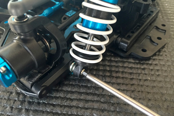
Step 22:
This step requires no special attention. However, for my build I used the Tamiya TRF Large Diameter Spring Set (Item 42278) and the TRF Large Diameter Retainer (Item 42192). The stock springs that come with the kit are far too soft for the current hot weather summer conditions at the Tamiya facility in sunny Southern California.
Step 23-24:
This step requires no special attention. However, for my build I used the TRF Damper Ball Connector (Item 42231). This ball connector allows you to keep the ball on the plastic shock cap thereby allowing you to unscrew the shock off rather than forcing it off every time you need to change springs. Use these ball connectors on the suspension arms as well to make changing shocks and springs even easier. You will need a headless 3mm screw to install into both shock towers and suspension arms for these Damper Ball Connectors to work. You can use any of Tamiya’s headless droop screws or the 3x8mm Hollow Titanium Screw to accomplish the easy upgrade. (Item 42238).

Step 25:
This step prepares your servo for installation. Note: You MUST use the included T4 or T5 plastic servo horn spline to get the correct spacing of the servo saver. Aftermarket servo arms and horns may not clear the front chassis braces. I decided to use the included T4 part for my Low-Profile Futaba servo.
Step 26:
This step requires no special attention except be aware that your motor tabs will sit on their side. There’s no way for the motor solder tabs to face up. There’s not enough clearance in the chassis.

Step 27:
Many people have asked me if using the motor cover is necessary. Omitting the cover is TCS legal, but I believe running it will help keep debris from reaching your spur and pinion.
Step 28:
You may have to shave the plastic servo holder in order to clear the servo cable that come out of your particular brand servo. Futaba servos do not require shaving the plastic servo mount, but other brands do.


Step 29:
This step requires no special attention. Install your servo as directed.
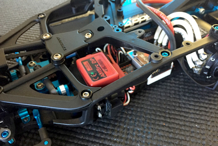
Step 30:
This step requires no special attention. This step usually takes me some time, as I like to wire everything nice and neat. By the time I get my car on the track I have gone through 3-4 wiring revisions.
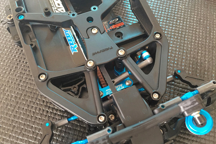
Step 31:
In this step you will be installing the motor guard and center chassis stiffeners. You don’t have to use the motor guard for TCS racing, but I would highly recommend doing so as it greatly protects the sensor cable from being torn out of the motor in a roll over or side impact. The weight savings is very minimal if you elect to remove it.

Tuning tip:
Under low traction conditions removing the center braces will help the chassis to flex more thereby increasing lateral traction.
Step 32:
This step is for racers using a standard size servo. Simply mount your receiver on top of the servo mount, as it won’t fit inside the main chassis compared to using a low-profile servo.
Step 33:
Pick the tires that best suit your local track or parking lot surface. For the purpose of my build I used my left over Reedy Race Sweep Spec Tire set.
Step 34:
This step requires no special attention, except I highly recommend switching out the plastic hex hubs for aluminum ones. The stock one’s work well, but you can easily lose the pin when switching tires frequently. I used the 5mm Aluminum Clamp Type Wheel Hub. (Item 53823). For tuning purposes you can also narrow the track by using the 4mm Aluminum Clamp Type Wheel Hub. (Item 53570).

Step 35:
This step requires no special attention. Install the front bumper and body post as directed. Note: You can replace the stock plastic bumper brace with the optional Carbon Bumper Support. (Item 54089). I also like to round off the foam bumper with my Dremel tool. This adds a nice finish to the bumper.
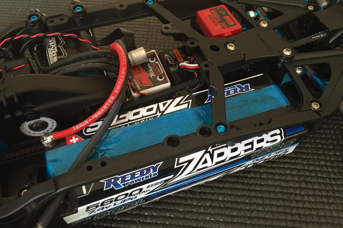
Step 36:
In this step you will be attaching the parts that will secure the battery to the chassis. I currently use the Reedy Zapper 5600, 6000, and 7400 packs for my touring cars. You will definitely need to use the A12 spacers to secure K3 for the proper clearance. Make sure to measure your specific battery for the correct spacers to attach K3 to the chassis. If you plan to use strapping tape, you won’t need this part at all. Simply run the strapping tape through both A7 loops and your set.
Plastic parts to secure the battery.

Tamiya strapping tape used to secure the battery.
Step 37-38:
The last two steps require no special attention. You are simply attaching the body post height adjusters to the posts. Make sure to leave one or two holes extra from the point where you finalize the optimal height for the body you decide to use. This will allow you to alternate between Tamiya Body Sets that you may want to try later on.
Further Hop-Up Options
The TA-07 Pro kit does not come with stabilizer bars. Stabilizer Bars are an essential tuning option. Luckily, the TRF418 Stabilizer Set (Item 42281) is a direct fit onto the TA-07, which is specifically called out at the back of the assembly manual. The set comes with 3 thickness bars for both the front and the rear. The TA-07 Pro kit comes with the necessary plastic mounts to secure the stabilizer set into place on the plastic bulkheads. The only thing you will need extra is the Stabilizer Rod Stopper. (Item 53827) The Rod Stopper securely centers the front and rear stabilizer.


Building tip:
The stabilizer bar is meant to move up and down freely. If it does not the stabilizer bar has become a torsion bar. That’s not what you want. Adjust the set screw that is threaded onto part A13 to the point where the bar stops moving excessively, up and down, between the bulkhead channel and the A13 part channel. Once the bar moves up and down freely and does not move side to side, you have a perfectly installed stabilizer.
The last Hop-Up Options to consider are carbon reinforced suspension parts. The stock TA-07 suspension parts are made of Fiberglass Reinforced Plastic. Under low traction and bumpy conditions their flex characteristics provide excellent traction. However, they can be inferior if you are running your car on surfaces that are hot, smooth, and have medium to high grip. Under these conditions you may want to opt to stiffer suspension components made of reinforced carbon plastic material.
Carbon reinforced suspension parts exhibit less material flex and allow the dampers to do more of the suspension work. It also allows the suspension system to behave more consistently because you’re not depending on the material flexing for suspension behavior. The car will also feel more responsive. You will need the following parts to change your suspension components into the carbon reinforced set up:
54580 RC Carbon Reinforced Hub Carrier 4 Degree
54570 RC TRF418 E Parts Carbon Reinforced Rear Uprights
54569 RC TRF418 D Parts Carbon Reinforced Suspension Arms
54568 RC TRF418 C Parts Carbon Reinforced Front Uprights
54546 RC Carbon Reinforced Hub Carrier 6 Degree
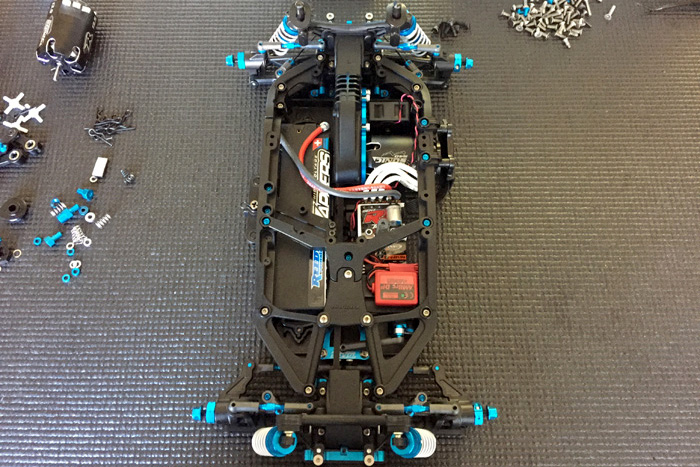
This concludes building the all-new TA-07 chassis! I have listed all the Hop-Up Options used for my test car.
In follow up articles and guides we will look at set-ups I have found to be good starting points at the Tamiya America Raceway. We’ll also look at the different motor positions and how they affect the handling of the car. For now, I leave you with a set up I found to be quick and easy to drive.
Finished Build:


Hop-Up Option Item used in this build:
42192 RC TRF Damper Large Diameter Retainer 4pcs
42216 RC Double Cardan Joint Shaft 44mm (2pcs)
42231 RC TRF Damper Ball Connector
42238 RC 3x8mm Hollow Titanium Screw (2pcs)
42278 RC Damper Large Diameter Spring Set TRF
42280 Fluorine Coating Lubricant 10ml bottle
42281 RC TRF418 Stabilizer Set Front/rear
51536 RC TRF417 V5 Swing Shaft Cap
51565 RC TRF419 Gear Diff Unit Aluminum Diff Joint 2pcs
53827 RC Stabilizer Rod Stopper
53989 RC Center Pulley 18T TRF501X
54121 RC HT Servo Saver Aluminum Horn
54208 RC 5x8mm Ball Connector Fluorine Coated
54209 RC 5x5mm Ball Connector Fluorine Coated
54704 RC TA07 Aluminum Steering Arm Set
54705 RC TA07 Aluminum Steering Bridge
9804852 RC Cross Shaft: 42285